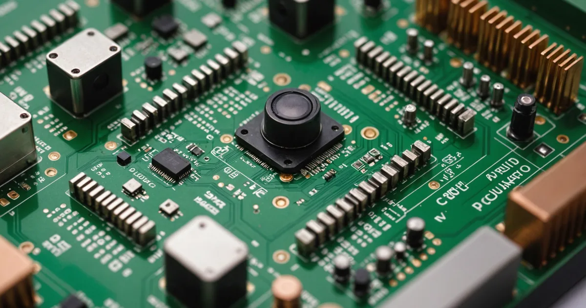
Deploying a vision system inside a commercial food holding cabinet is a different engineering problem from deploying a camera in most other environments. The typical design assumption for embedded vision hardware is that the operating environment is more or less controlled: moderate temperature, low humidity, predictable lighting, no airborne contaminants. Commercial kitchen environments violate every one of those assumptions, and the violations compound each other.
This post is a technical account of the specific constraints we encountered designing Cook-e's embedded vision module for the interior of a commercial hot-holding cabinet, and the decisions we made in response. It is written for engineers who build for similar environments, not as a product pitch.
Thermal environment: the cabinet's interior is not a controlled space
A hot-holding cabinet maintains food at temperatures in the 63 to 80 degrees celsius range at the food surface. The air temperature inside the cabinet is lower than that, because the heating elements target the tray surfaces, not the air volume. But "lower than 80 degrees" is still a demanding thermal environment for electronics.
The first constraint is the operating temperature range of the image sensor. Most commercial CMOS image sensors specify a maximum operating temperature of 70 to 85 degrees celsius at the sensor package. An embedded module positioned in the upper interior of the cabinet, capturing frames of the tray surfaces below, is in an air temperature that may reach 55 to 65 degrees celsius under steady-state operating conditions. This is within tolerance, but it leaves a small margin. Any additional heat from the module's own processing electronics narrows that margin further.
Our approach was twofold. First, we selected a sensor rated to the upper end of commercial-grade specifications and verified its thermal performance in a purpose-built thermal soak test rig that replicates the cabinet interior conditions. Second, we kept the on-module processing minimal: the sensor captures frames and transmits them via a short cable to a compute module located outside the cabinet interior, in a lower-temperature compartment at the base of the cabinet. The heat budget for the sensor module is dominated by the sensor itself, not by inference compute. This is a deliberate architectural split.
Humidity and condensation
Hot food in a closed cabinet produces steam. The relative humidity inside the cabinet during operation is high and variable: it spikes when fresh hot food is loaded, drops when the door opens and drier air enters, and stabilises at an elevated level during normal hold operation. We measured relative humidity levels inside a cabinet during a representative service cycle and found peaks above 85% RH during the first 15 minutes after loading hot food.
High humidity creates two problems for embedded electronics. First, condensation on optical surfaces. A camera lens that fogs is not useful. Second, condensation on PCB surfaces, which creates conductivity bridges between traces and can cause component failures over time.
For the optical path, the solution is a sealed housing with a sapphire window element. Sapphire is used because its surface energy profile resists condensation film formation better than standard optical glass, and because it is mechanically harder and therefore more resistant to cleaning damage. The window is sealed to the housing with a silicone gasket rated for repeated thermal cycling. There is no air path from the cabinet interior into the optical cavity.
For the PCB, we use conformal coating on the sensor module board and a desiccant pack in the sealed housing cavity. The desiccant is sized for a 12-month service interval, at which point it needs replacement. This is a maintenance item, not a design failure. We made a deliberate choice to use a serviceable desiccant rather than an oversized hermetically sealed cavity, because the latter adds significant cost and bulk for marginal lifetime extension in this use case.
Grease aerosols
Grease in the air is a more significant problem than most electronics engineers anticipate when they first encounter the commercial kitchen environment. When protein-rich food cooks, it releases vaporised fats that condense on cooler surfaces. In an enclosed cabinet, the camera lens housing is a surface that is maintained at a lower temperature than the food (by design, to protect the electronics). It is, therefore, a condensation point for grease aerosols.
Grease on the sapphire window is not the same as humidity condensation. It does not evaporate when the cabinet cools down. It builds up as a film with each service cycle and attenuates the image over time, degrading classification accuracy.
The solution is a combination of material selection and a cleaning protocol. The sapphire window is easier to clean than glass because it is harder and does not scratch with normal cleaning materials. We provide a cleaning spray and wipe as part of the maintenance kit, and the dashboard software tracks the number of service cycles since the last window cleaning event and prompts the operator when a cleaning is due.
We also designed the housing geometry to minimise grease accumulation: the window face is recessed slightly within a cylindrical collar that acts as a drip edge, so grease aerosols that condense on the housing exterior do not run down onto the window face. This reduced the cleaning interval in our test installations from every 2-3 days to every 7-10 days under normal commercial use conditions.
Illumination design within the cabinet
Consistent illumination is a prerequisite for reliable visual classification. If the lighting inside the cabinet varies between frames or between service cycles, colour-channel analysis is unreliable because the camera is seeing a different illumination spectrum, not a different food state.
We specified a narrow-band LED array for the cabinet interior with a fixed colour temperature of 4000K and a colour rendering index (CRI) above 90. These are not arbitrary numbers: 4000K is close enough to daylight to produce natural colour rendering on food surfaces, and CRI above 90 ensures that the spectral distribution of the light is complete enough that the camera sensor captures colour information that is useful for food-type differentiation.
The LED array is controlled by the cabinet's microcontroller, not by a simple on/off switch. The array runs at a fixed PWM frequency that is above the sensor's frame rate to avoid banding artefacts in captured images. The array's current is regulated to maintain consistent luminosity as the LEDs age and as junction temperature varies with the cabinet's operating temperature. LED luminosity at constant current decreases as junction temperature rises; compensation for this was necessary to avoid systematic illumination drift over a service cycle.
Cable routing and connector selection
The cable between the sensor module and the compute module runs through the cabinet's structural body from the upper interior to the lower base compartment. This cable passes through a thermal gradient: the interior end is at 55 to 65 degrees celsius; the base compartment end is at ambient plus moderate electronics heat, typically 35 to 45 degrees celsius during operation.
Standard PVC-insulated cables are rated to 70 or 80 degrees celsius in most commercial grades, which provides adequate margin for the interior end in normal operation. We used PTFE-insulated cable in the first prototype because we were not yet confident in the steady-state interior temperature. The PTFE cable is mechanically stiffer and harder to route, which added assembly cost. After accumulating temperature data from prototype installations, we shifted to a high-temperature silicone-insulated cable specification that is rated to 200 degrees celsius, is more flexible, and is less expensive than PTFE in the gauge we needed.
Connectors at both ends use sealed M8 circular connector formats with IP67 rating. This is overcautious relative to the actual humidity level in the base compartment, but M8 circular connectors are standard in industrial embedded vision systems and their connector retention is more reliable than the latching mechanisms on smaller proprietary connectors when the equipment is being cleaned and the cable is being moved during that process.
What we did not get right on the first iteration
The thermal soak test for the sensor module was conducted at a steady-state temperature. We did not adequately test the thermal cycling behaviour: the repeated expansion and contraction of the housing as the cabinet cycles between ambient and operating temperature multiple times per day. The first production housing design used an aluminium body with a polymer front element, and the differential thermal expansion between the two materials cracked the adhesive bond at the interface after approximately 60 thermal cycles in accelerated life testing. We redesigned the housing with an all-aluminium construction and a sealed bayonet fit for the window element, which survived 300 thermal cycles without failure in subsequent testing. The lesson was not novel, it is standard knowledge in industrial electronics, but it required us to actually run the test to find the failure mode.
The commercial kitchen environment is not hostile in a way that makes it impossible to deploy embedded electronics. It is hostile in a way that requires each environmental factor to be worked through methodically, without assuming that standard consumer or commercial electronics design practice transfers directly. Heat, humidity, grease, and thermal cycling are each tractable problems. The work is in not assuming any of them is solved until you have tested it.